
Pt100 Sensors change their electrical resistance in dependence on temperature. In order to record the output signal, the line drop created by a constant measuring circuit is measured.
- Acc. to the Ohm ́s law the following is valid for this line drop: U = R x l
In order to avoid the heating of the sensor, a small measuring circuit shall be chosen. A measuring circuit of 1 mA does not have any considerable impact. This current creates a line drop of 0,1 V with a PT 100 at 0°C. This measuring voltage has tobe transferred to the display for evaluation as accurately as possible. We distinguish between four connection techniques:
2 - Wire Circuit
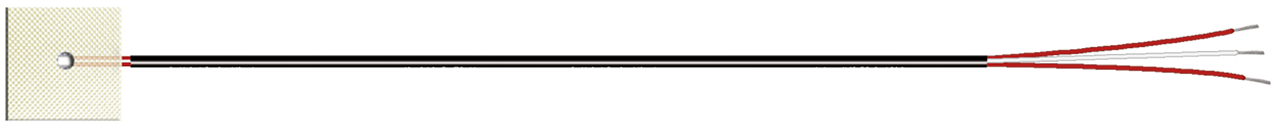
Pt100 temperature sensor with 2-wire connection
The connection between evaluation unit and thermometer is made by a 2 conductor cable. Like any other electrical conductor, such a cable has a resistance itself in serial mounting with the resistance thermometer. Thus, the two resistances are added that is interpreted as a higher temperature by the processing unit. In case of far distances the cable resistance can amount to several ohms and in this way falsify the measuring result.
Configuration example: Pt100 temperature sensor with 2-wire circuit

Example:
cable section: 0,35 mm2
spec. resistance: 0,0175 Ω mm² m-1
cable length: 50 m
cable material: copper (E-CU)
R = 0,0175 Ω mms² m-1 x 2 x 50 m/ 0,35 mm²= 5,0 Ω
5,0 Ω correspond to a temperature change of 12,8 °C with a Pt 100. In order to avoid this fault, the cable resistance is compensated electrically: The electronic unit is designed in a way that always a cable resistance of 10 Ω is considered. When the resistance thermometer is connected, a balancing resistance is connected into one of the measuring cables and, first of all, the sensor is replaced by a 100-Ω-resistance.
Now the balancing resistance is changed as long as the display unit shows 0°C. The balancing resistance together with the cable resistance amount to 10 Ω. In most cases, the balancing resistance wire is wound so that the balance is done by unwinding the wire. Due to this extensive balancing work and the unknown temperature impact on the measuring cable, the 2-wire circuit is declining.
3 - Wire Circuit
Pt100 temperature sensor with 3-wire connection
In order to minimize the influences of the cable resistance and its temperature dependant fluctuations, the 3-wire circuit is frequently used instead of the above mentioned 2-wire circuit. Therefore, an additional cable is led to a contact of the RTD. Thus, 2 measuring circuits are created, one of them being used as reference.
Due to the 3-wire circuit, the cable resistance is compensated with regard to its amount as well as with regard to its temperature dependence provided that the 3 conductors have the same characteristics and are exposed to the same temperature. Therefore, a compensation of the cable resistance is no longer necessary.
Conficuration example: Pt100 sensor with 3-wire circuit

4 - Wire Circuit
Pt100 temperature sensor with 4-wire connection
The best connection type for resistance thermometers is the 4-wire circuit. The measuring result is neither influenced by the cable resistance nor by their temperature dependent fluctuations. A compensation of the cable resistance is no longer necessary. The thermometer is fed with the measuring circuit via cable.
Is the incoming resistance of the topped electronics a multiple of the cable resistance, it is to be neglected. Thus the voltage drop is independent from the characteristics of the line. For the 3-wire as well as for the 4-wire circuit, it has to be considered that the circuit is not always led to the measuring element. The connection of the sensor to the connection head in the armature, the so called inner circuit is often done in a 2-wire circuit. This results in the problems of a 2-wire circuit – even to a smaller extent.
Conficuration example: Pt100 temperature sensor with 4-wire circuit

Pt100 inner conductor colors
Pt100 Connection and circuit of the conductors (inner conductor) | ||||
| Measuring element | Pt100 2-wire connection colors | Pt100 3-wire connection colors | Pt100 4-wire connection colors | Pt100 2-wire with loop |
| Pt100 | red/white | red, red/white | red, red/white, white | red, white/ blue, blue |

2 x Pt100 inner conductor colors
Circuit of the inner conductors | |||
| Measuring element | 2-Leiter Schaltung Farben | 3-Leiter Schaltung Farben | 4-Leiter Schaltung Farben |
| 2 x Pt100 | yellow, yellow / white, white | red, red / black, black / white | red, red / white, white / black, black / white, white |

3 x Pt100 inner conductor colors
Circuit of the inner conductors | |
| Measuring element | 2-wire circuit colors |
| 3 x Pt100 | red, red / white, white / yellow, yellow |

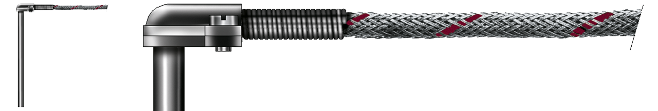
Pt100 Sensors Overview - Basic Types and Construction Forms
Pt100 temperature sensors are available in various designs and types. In the following overview you will find common types and designs of Pt100 and Pt1000 sensors that are frequently used. We can customise other Pt100 temperature sensors to your individual requirements and application on request. Please contact the SAB team.


More information about Pt100 sensors.