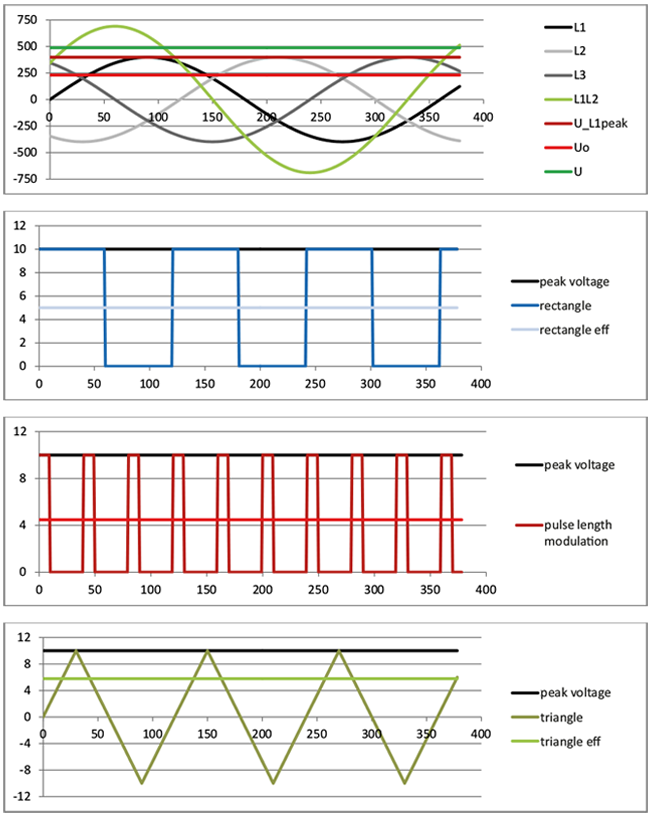
An important value for the application of a cable is the voltage rating. Depending on the cable application however, there are different voltage ratings that are not always interchangeable among each other. For classic applications at an AC voltage source mostly the effective value (Ueff) is indicated. Due to the alternating voltage curve this value corresponds to the load that a constant direct voltage would apply. The max. peak voltage is almost 50 % higher. The English term for the effective value is “RMS” for “RootMean-Square” that indicates the calculation of the mean value.
Peak operating voltages are mostly indicated for not periodical applications as for example data cables -analogue or digital-. For cables that are only short term highly loaded so that the indication of the effective value or regularly occurring peak voltages do not make sense, either application-related indications are made (for example the “ignition voltage” of cables for gas discharge lamps) or the “test voltage” used during production in order categorize the performance capability of a cable. Both indications reflect only short term load in the service life of a cable and therefore, are mostly higher with the same insulation than the indications of permanent load as for example peak voltage or RMS value (root mean square).
Another important aspect is the voltage towards environment (“earth”, “mass”) or towards other conductors. Towards environment there is only one effective insulation layer, against the second conductor, however, two layers. Therefore, the indication core/core (U) is mostly higher than core/mass (U0). The classical examples are here three phase current systems for which the phase shift of voltage on the conductor of 120° leads to the fact that an alternating voltage between the cores occurs that is exactly the factor √3 higher than the voltage of the conductor against mass.
Acc. to standard VDE 0298-3 the following interrelations result for “the highest permanently allowed operating voltage Ub,max” under consideration of load reserves:
| nominal voltage | highest permanently allowed operating voltage Ub,max | |||
| U0/U [V] | AC conductor/ earth [V] | AC conductor/conductor [V] | DC conductor/ earth [V] | DC conductor/conductor [V] |
| 230/400 V | 254 | 440 | 330 | 660 |
| 300/500 V | 318 | 550 | 413 | 825 |
| 450/750 V | 476 | 825 | 619 | 1238 |
| [kV] | [kV] | [kV] | [kV] | [kV] |
| 0,6/1 kV | 0,7 | 1,2 | 0,9 | 1,8 |
| 1,8/3 kV | 2,1 | 3,6 | 2,7 | 5,4 |


